
Cleanroom Airlock Doors: How to Control Entry and Contamination
1. Introduction
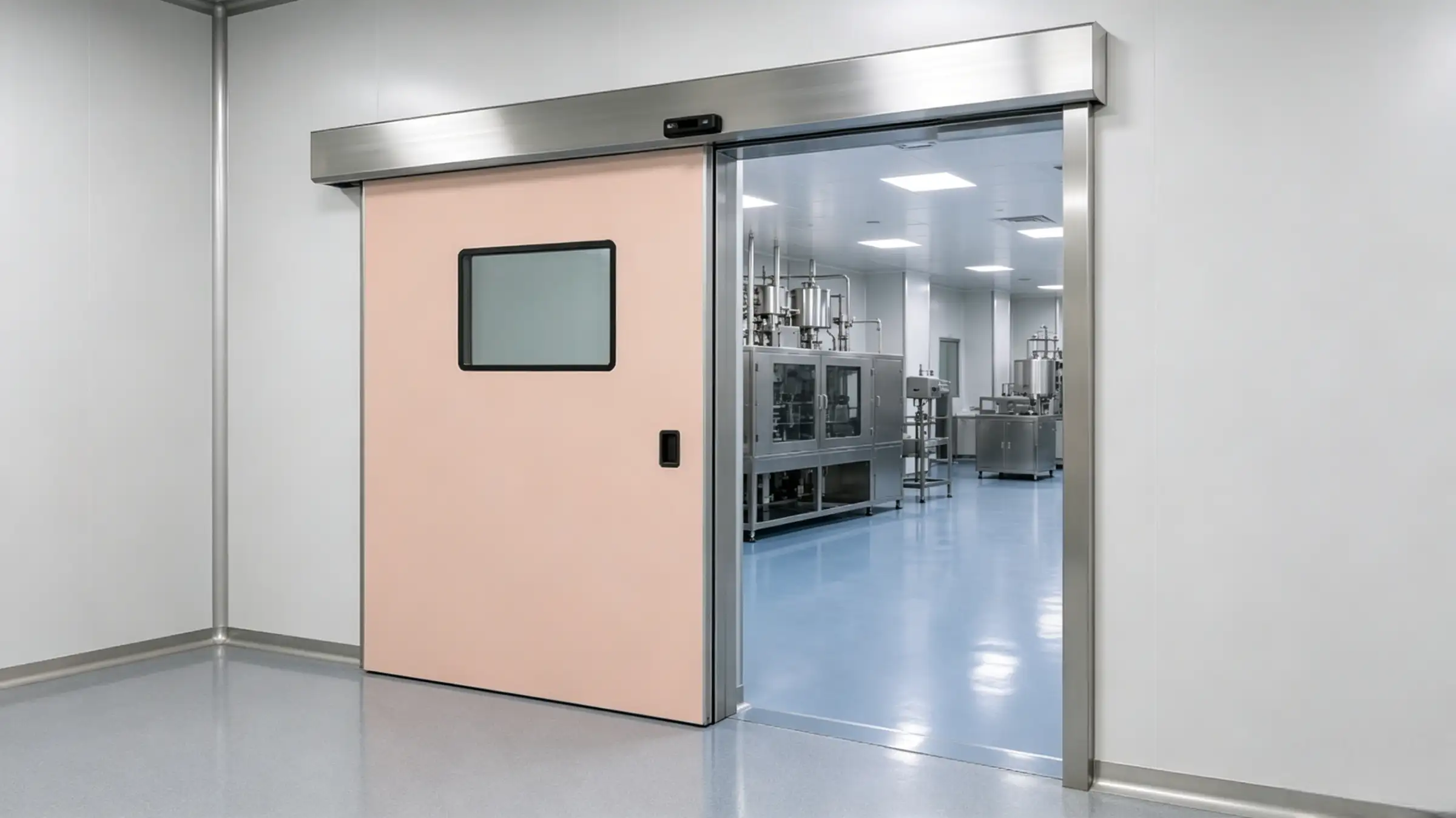
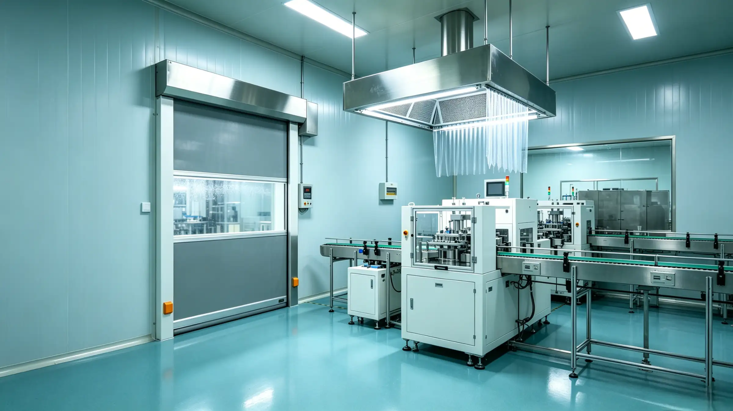
In highly regulated manufacturing, microenvironmental control directly dictates product yield and compliance. As the primary barrier between classified zones, cleanroom airlock doors serve a critical function: interrupting particulate migration, maintaining pressure gradients, and enforcing strict personnel and material routing.
Modern airlocks have evolved from simple physical partitions into integrated control hubs that combine airflow management, intelligent interlocking, and real-time monitoring. This article outlines the engineering principles, control strategies, validation protocols, and compliance requirements necessary to design and operate these systems effectively.
2. Engineering Principles & Design Specifications
Airlock design is a systematic engineering exercise grounded in fluid dynamics and contamination modeling. Core control logic hinges on the strategic selection of pressure gradient profiles:
- Cascade Configuration: Pressure decreases stepwise across zones (e.g., Grade B → C → D, ΔP = 10–15 Pa), establishing unidirectional clean airflow.
- Bubble Configuration: The airlock maintains the highest pressure relative to adjacent zones (+5 to +10 Pa), creating bidirectional containment for HPAPIs or Grade A core zones.
- Sink Configuration: Internal pressure is maintained lower than surrounding areas to ensure zero containment breach, mandatory for BSL-2/3 facilities.
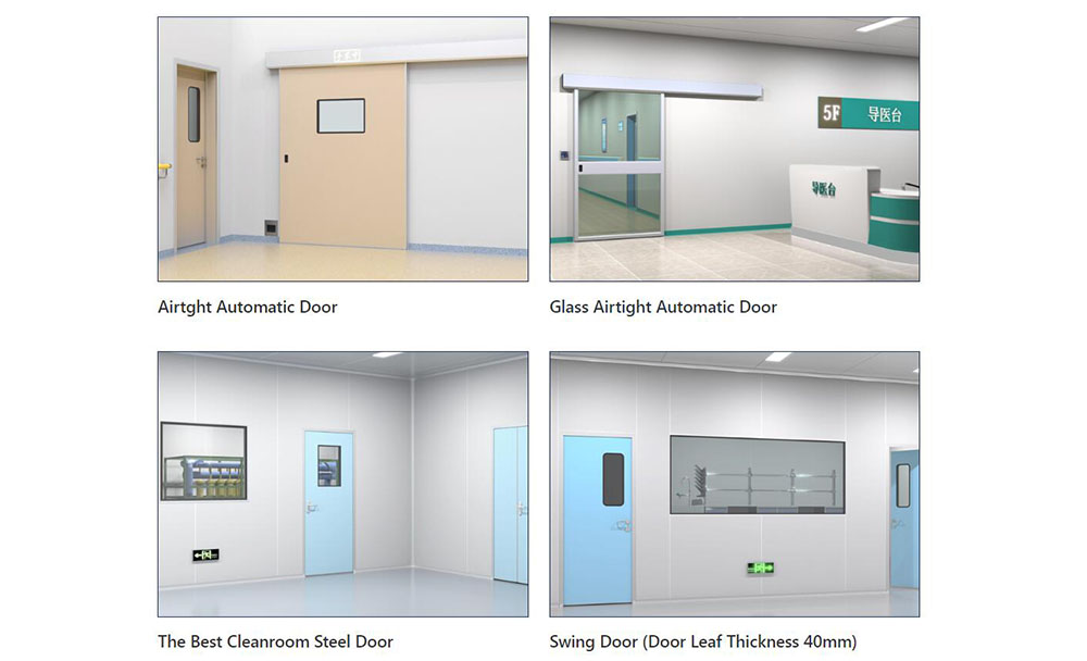
ISO 14644-4 recommends that static cleanroom pressure differential between adjacent zones be ≥10 Pa, with dynamic fluctuations controlled within ±3 Pa to prevent airflow reversal during door actuation. Regarding cleanroom door specifications, modern engineering adheres to the following benchmarks:
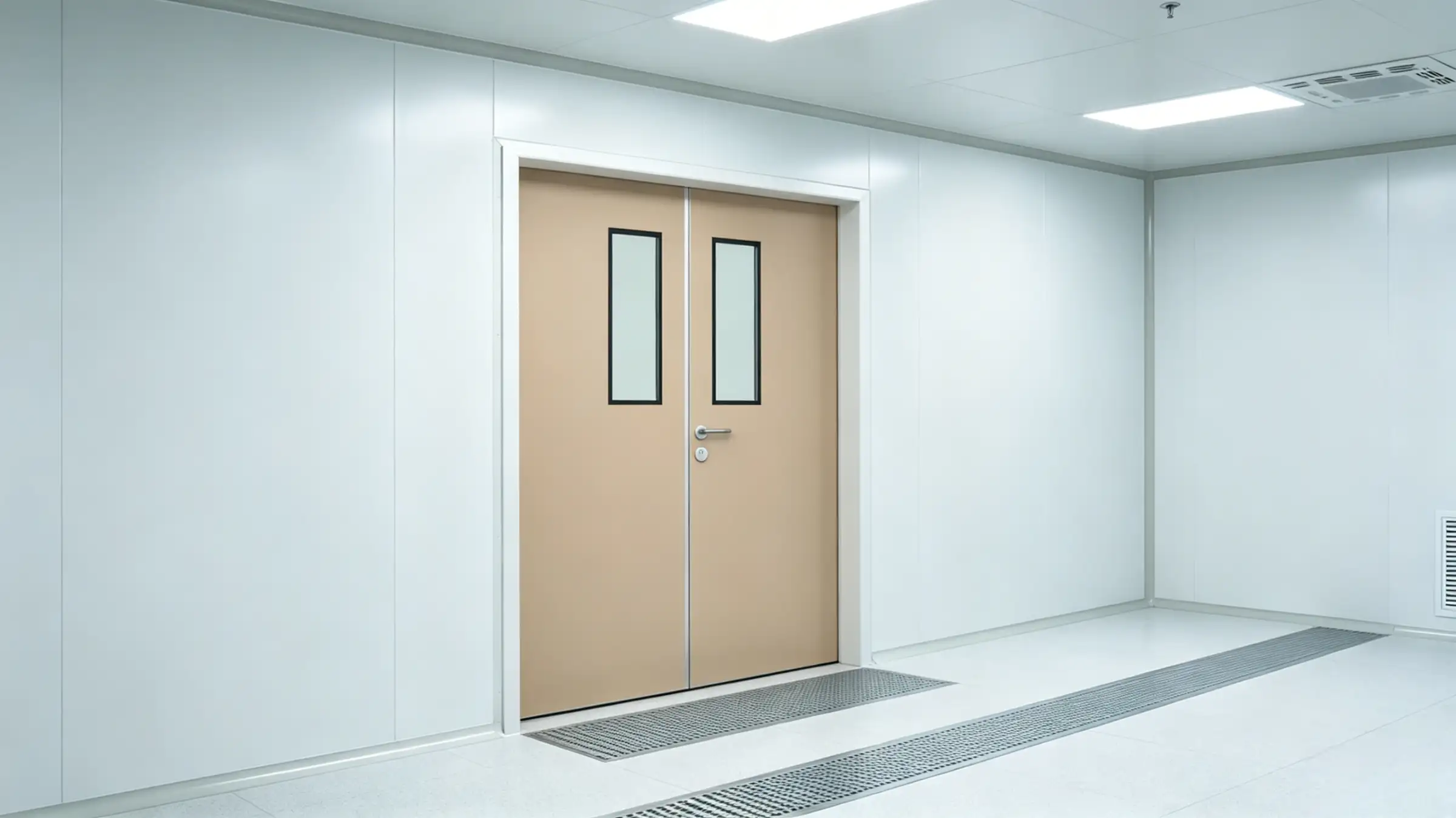
- Substrate & Surface Finish: 316L stainless steel electropolished to Ra ≤0.4 μm to reduce particulate adhesion and biofilm risk.
- Sealing System: Dual-lip silicone or EPDM gaskets engineered for 25–30% compression, validated for 1,000+ hours of VHP or ozone compatibility.
- Structural Details: Frameless construction, R-angles ≥50 mm, concealed fasteners, and micro-sloped flooring (0.5–1% gradient) to eliminate cleaning dead zones.
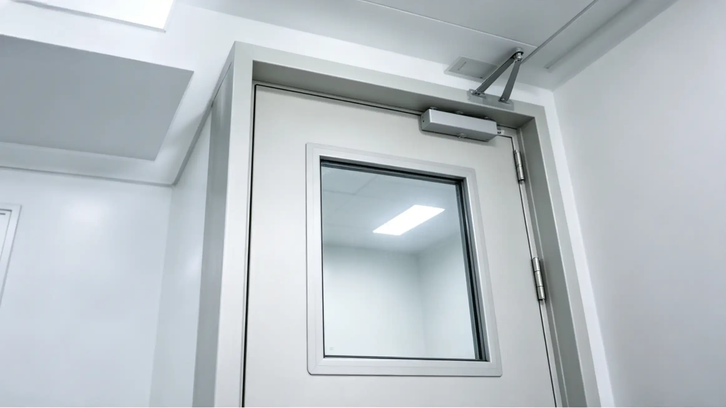
Interlock control functions as the operational central nervous system. The airlock interlock system has transitioned to PLC/SCADA architectures, governed by strict logic:
- Simultaneous door opening is prohibited, with electrical response ≤1 second and torque-limited jam protection.
- Anti-tailgating algorithms couple door sensors with infrared curtains; unauthorized following triggers alarms and locks access.
- Fail-safe modes default per fire and biosafety codes during power loss, with timestamped logging uploaded to the BMS platform.
3. Personnel & Material Entry Control Strategies
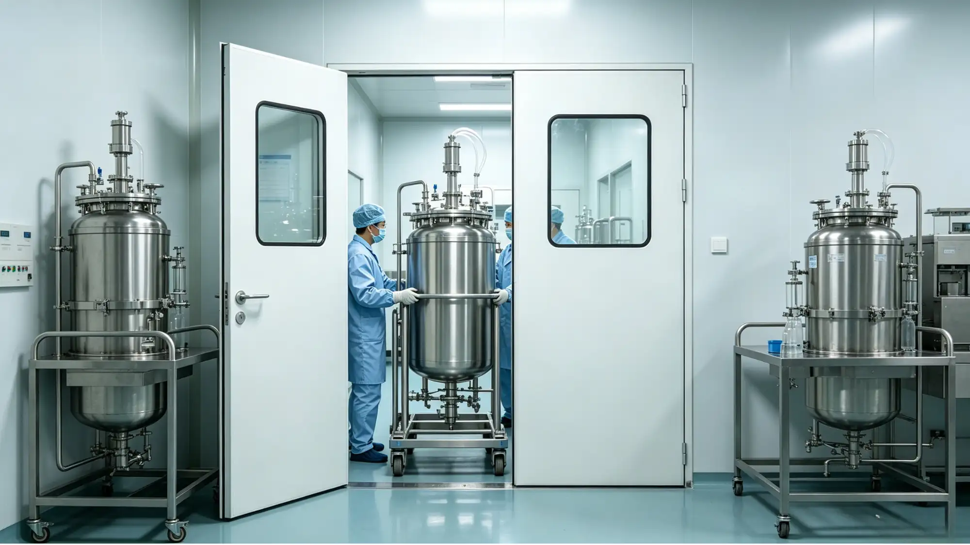
Personnel entry represents the most significant contamination vector. Standard routing must strictly enforce physical separation and aerodynamic buffering. A typical control sequence for a personnel airlock includes:
- Baseline gowning in the outer change room, followed by RFID or biometric verification.
- Outer door closure; inner door access releases only after pressure stabilizes (ΔP ≥10 Pa).
- If integrated with an air shower, directed airflow ≥0.5 m/s activates for ≥15 seconds (≥90% removal efficiency for ≥0.5 μm particles).
- Inner door opening permits cleanroom entry, with all events logged, including privilege matrices and cycle counts.
Modern access systems are intrinsically linked to electronic SOPs. Incomplete gowning or unauthorized dwell times trigger automatic privilege degradation. All records must generate tamper-evident audit trails compliant with FDA 21 CFR Part 11 and EU GMP Annex 11.
Material entry control focuses on deboxing and surface decontamination. A material airlock typically implements double-packaging. To effectively prevent cross contamination in cleanroom airlocks, facilities must establish standardized transfer protocols:
- VHP decontamination: Achieves ≥6 Log Reduction for bacterial spores. Requires catalytic breakdown to reduce residuals <1 ppm, with typical cycles of 45–60 minutes.
- Dry fog systems: Ideal for complex geometries. Operating humidity must stay at 40–60% RH to prevent condensation.
- UV-C (254 nm): Effective only on direct line-of-sight surfaces. Requires ≥60 mJ/cm² dose and serves as a supplementary measure.
- Inert gas purging: ISO Class 3–5 suites frequently integrate N₂ purging (dew point ≤-60°C) and ionized air curtains to control AMC and electrostatic attraction.
Airlock cycles must enforce an "entry → decontamination → pressure stabilization → exit" sequence. Recovery time targets are ≤15–20 minutes (per ISO 14644-3). Material carts must be color-coded and strictly zoned; cross-area usage is prohibited.
4. Core Contamination Control Mechanisms & Operational Logic
Containment relies on directional airflow, surface inertness, and behavioral compliance. Particulate control depends on terminal filtration and upstream plenum design, maintaining supply air uniformity ≥85%. In a HEPA filter airlock configuration, filters require periodic DOP/PAO aerosol leak testing (≤0.01% leakage), with upstream static pressure maintained at 150–250 Pa. In high-traffic zones, air curtains deploying directional jets at 2–3 m/s minimize cross-mixing during door actuation.
Operational strategies must match production pacing. Common modes for cleanroom airlock door pressure control include:
- Normally Closed: Deployed in Grade A/B zones (<5 cycles/hour). Relies on differential sensors for static gradients.
- Pressure-Triggered: ΔP sensors modulate EC variable-frequency fans for on-demand compensation (±3 Pa fluctuation), reducing energy use by >30%.
- Timed/Cycle Mode: Used for fixed-batch transfers, synchronized with automated recovery countdowns.
- Manual/Auto Bypass: Activated for maintenance or validation. Requires dual authorization, deviation logging, and post-restoration recovery testing.
Human factors remain critical. SOP deviations (improper gowning, running, tailgating) drive pressure collapse and particulate excursions. Multidimensional monitoring enables real-time intervention:
- Three consecutive particulate limit breaches automatically extend recovery cycles and trigger alarms.
- Door actuation >15 cycles/hour mandates routing and scheduling reviews.
- AI behavioral recognition detects non-compliance, temporarily freezes access privileges, and generates CAPA work orders.
5. Validation, Monitoring, Maintenance & Compliance Management
Lifecycle management requires a rigorous validation framework. cleanroom airlock door validation IQ OQ PQ forms the cornerstone of compliant operation:
- IQ Phase: Verification of material certifications, gasket records, wiring schematics, and BMS protocols. Confirmation against P&IDs and layout drawings.
- OQ Phase: Testing of interlock response (≤1 s), pressure stability (≤±3 Pa), aerosol leakage (≤0.01%), smoke visualization, and alarm integration.
- PQ Phase: Simulation of extreme failures (door jam, power loss, HVAC shutdown) to verify 5-minute safe recovery. Completion of settle plate and active air sampling.
Continuous monitoring must cover ΔP, temperature, humidity, particulate counts, door status, and interlock logs at ≥1 Hz sampling frequency. Alarm thresholds should be tiered (Warning/Action/Stop). During FDA compliance for cleanroom airlocks inspections, data integrity, privilege tiering, and audit trail completeness are mandatory focal points. All manual overrides require electronic signatures and documented rationale.
Preventive maintenance is foundational. Addressing how to maintain cleanroom airlock doors requires a standardized checklist:
- Gasket service life spans ~2–3 years (~50,000 cycles). Compression set must be ≤20%; micro-cracks mandate immediate replacement.
- Differential sensors require biannual calibration. Drift >±0.5 Pa necessitates replacement or zero recalibration.
- Hinges and closers require cleanroom-grade PFPE grease only. Silicone or mineral oils cause HEPA contamination.
- Pre-filters need quarterly replacement. Log pressure drop curves (initial: 50–80 Pa; final: ≤250 Pa). Abnormal rise indicates duct fouling.
Fault Tree Analysis shows pressure loss typically stems from clogged fan filters or stuck dampers. VHP residue alarms usually indicate saturated catalytic converters or off-spec conditions (optimal: RH 40–60%, T 20–25°C). Facilities must implement closed-loop CAPA matrices to ensure deviations are traceable and corrections are quantifiable.
6. Conclusion
Cleanroom airlocks are critical control nodes, not mere architectural components. Effective contamination containment requires precise engineering, rigorous SOP adherence, and lifecycle validation backed by uncompromising data integrity. By integrating these systems holistically with HVAC infrastructure and quality management protocols, facilities can maintain stable, auditable, and compliant microenvironments.
-
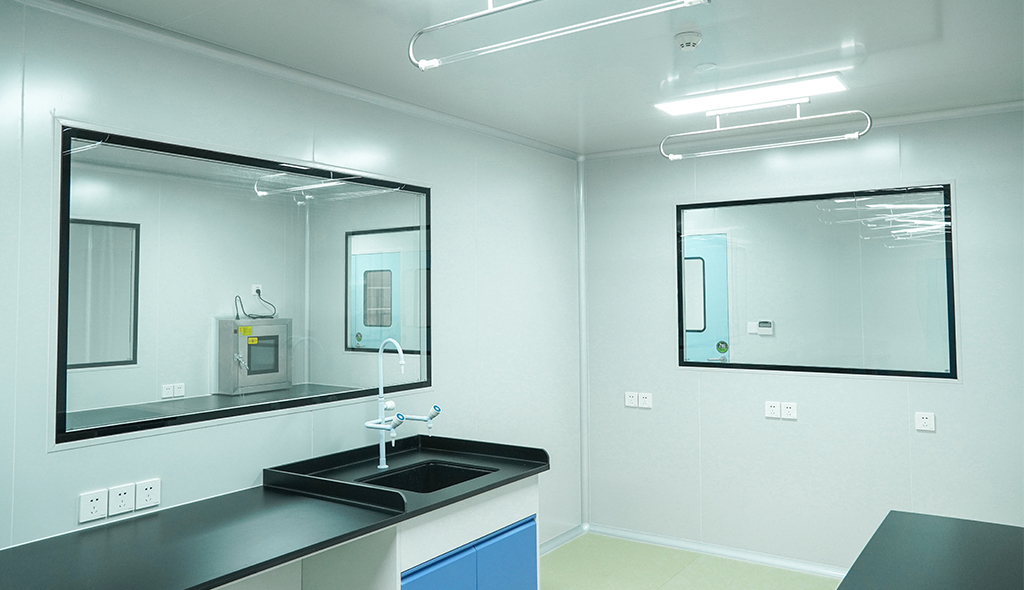 Cleanroom Glass Windows Are The Key to Maintaining a Clean Environment
 -
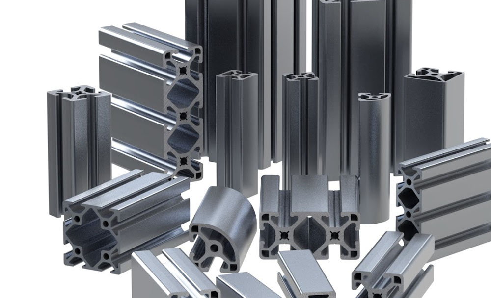 Top Aluminium Profile Manufacturers in China: Leading the Global Market
 -
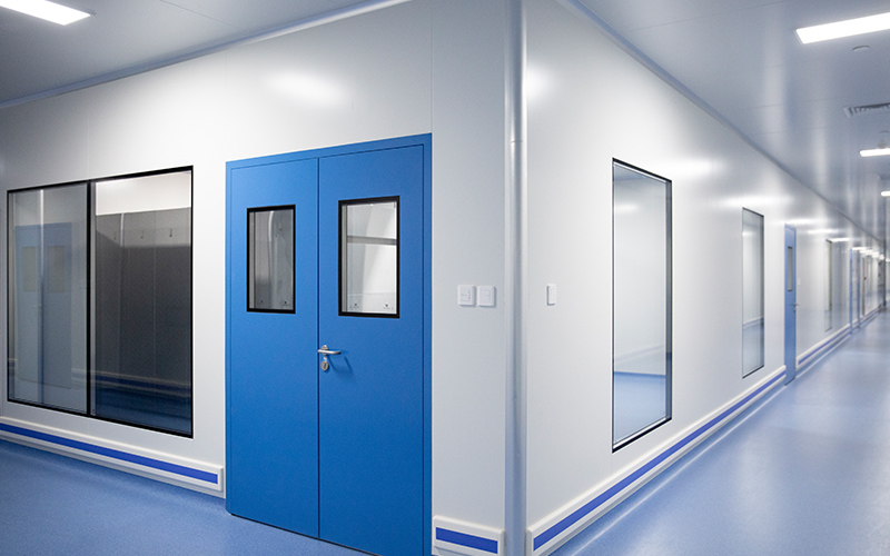 The Evolution of Air Tight Sliding Doors
 -
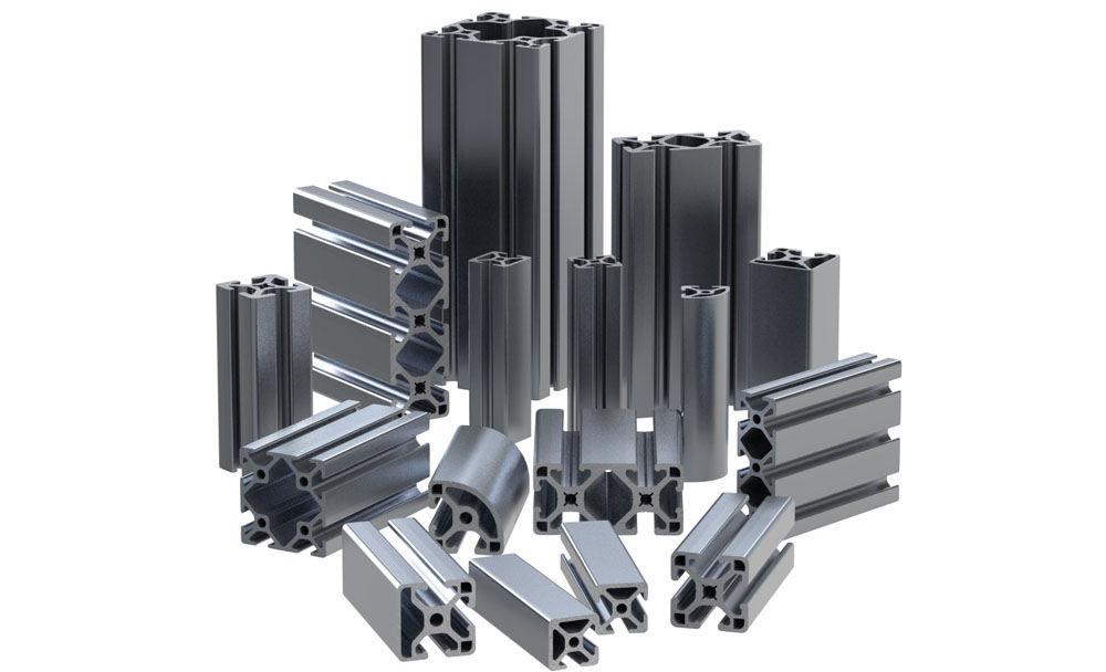 AHU Aluminium Profile: A Comprehensive Guide
 -
 The Importance of Choosing the Right Cleanroom Door in Vietnam
 -
 The Benefits of Hospital Automatic Doors: Enhancing Efficiency and Safety
 -
.jpg) The Best Bathroom Door Manufacturers - Unlocking Endless Possibilities!
The Best Bathroom Door Manufacturers - Unlocking Endless Possibilities! -
 Unlock the Possibilities with AJ Manufacturing Doors
 -
 Make a Statement with Manufactured Home Interior Doors!
 -
 what is aluminum profile? Aluminum Profiles for Your Home is the best option
-
 Cleanroom Sliding Door Selection Guide for GMP Facilities
 -
 Hygienic Doors Selection Guide: Food, Pharma, Healthcare
 -
 X-Ray Room Doors for Hospitals: Shielding, Access and Cleanability
 -
Cleanroom Roll-Up Doors for Fast Access in Controlled Areas
-
 Medical Swing Doors vs Sliding Doors: How to Choose for Healthcare Spaces
 -
 Cleanroom Vision Panel Doors: Visibility Without Compromising Hygiene
 -
 Fire Rated Cleanroom Doors for Controlled Environments
 -
 Cleanroom Double Doors for Equipment Access and Material Transfer
 -
 Laboratory Doors for Chemical, Biotech and Testing Facilities
 -
 Pharmaceutical Facility Doors: Choosing the Right Door for Each Production Zone


-

Home
-

Tel
-

Email
-

Contact


Guangzhou Yizhong Aluminum Industry Co., Ltd.
We are always providing our customers with reliable products and considerate services.
We are always providing our customers with reliable products and considerate services.
Speak Your Mind