
Custom vs Off-the-Shelf: Cleanroom Aluminum Profiles Compared
I. Cleanroom Aluminum Profiles: The Structural and Functional Backbone of Modern Controlled Environments
In advanced manufacturing, biopharmaceutical production, semiconductor packaging, and sterile medical applications, cleanrooms have evolved beyond simple enclosures. They are now integrated, dynamic systems — multidisciplinary platforms where environmental control, equipment integration, and regulatory compliance converge. At the core of this system lies the cleanroom aluminum profile: not merely a structural element, but the physical framework and functional interface that governs stability, maintainability, compliance, and lifecycle cost.
Whether constructing a modular cleanroom framework or engineering an electronics-grade aluminum system, the profile selection is a foundational engineering decision — not a procurement afterthought.
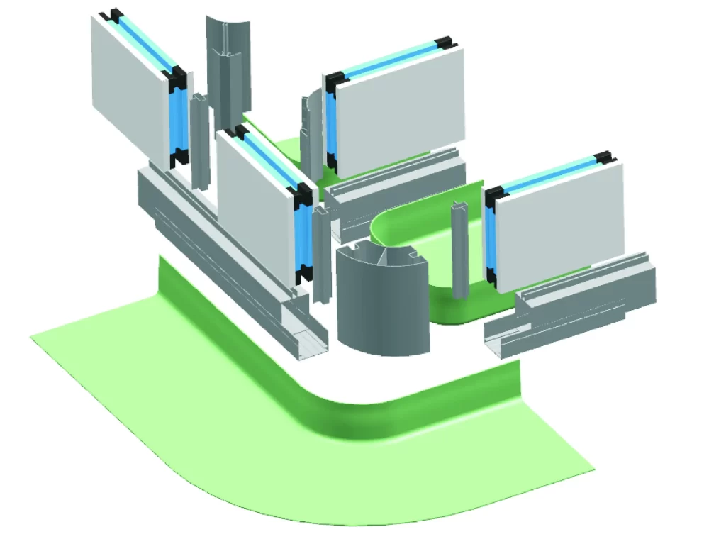
The Multifunctional Role of Aluminum Profiles in Cleanroom Design
Cleanroom aluminum profiles serve four critical engineering functions:
- Structural Load-Bearing Elements: Designed to support FFUs, lighting arrays, process equipment, and utility conduits — requiring defined stiffness, bending resistance, and fatigue endurance.
- Airflow and Pressure Boundary Components: Engineered cross-sections and integrated sealing features maintain unidirectional pressure gradients and prevent particulate ingress.
- Equipment Integration Interfaces: Pre-engineered T-slots, mounting rails, sensor channels, and grounding paths enable rapid, repeatable, and vibration-isolated equipment installation.
- Modular Assembly Platforms: Standardized geometries support prefabrication, rapid deployment, and reconfiguration — essential for scalable, future-proof cleanroom infrastructure.
The Consequences of Suboptimal Profile Selection
Incorrect profile selection triggers cascading system failures — with impacts far exceeding material cost:
- Airflow Disruption: Insufficient rigidity or compromised sealing induces pressure instability, degrading laminar or turbulent flow patterns and enabling particle accumulation.
- Particulate Excursions: Surface roughness, joint leakage, or geometric dead zones violate ISO 14644-1 particle concentration thresholds.
- Structural Resonance: Modal frequencies aligned with rotating equipment (e.g., fans, pumps) induce fatigue, fastener loosening, and seal degradation.
- Regulatory Noncompliance: Failure to satisfy GMP Annex 1 (“no shedding, no dead zones, cleanable surfaces”) or SEMI F73 (“low outgassing, ESD-safe surfaces”) results in audit citations or project rejection.
- Costly Rework: Post-installation modifications can cost 3–5x the original investment and delay operational readiness by months.
Strategic Selection: Standard vs. Engineered Profiles
The choice between standard (off-the-shelf) and engineered (custom) aluminum profiles is not binary — it is a strategic allocation of resources based on performance requirements, risk tolerance, and lifecycle value.
- Standard Profiles: Best suited for projects with well-defined boundaries, moderate performance demands, and cost or schedule constraints. Emphasize supply chain maturity, rapid deployment, and interchangeability.
- Engineered Profiles: Required for applications demanding integrated functionality, enhanced sealing, structural optimization, or regulatory alignment. Prioritize performance, compliance, and risk mitigation.
Hybrid strategies are often optimal: standard profiles for primary framing to control cost; engineered profiles at critical interfaces, sealing zones, or load-bearing nodes to ensure performance.
II. Standard Cleanroom Aluminum Profiles: Scope, Suitability, and Limitations
1. Definition and Specifications
Standard cleanroom aluminum profiles conform to established dimensional, surface treatment, and compatibility norms — ensuring broad interchangeability and mature global supply chains. These cleanroom-grade extrusions serve as the default selection for the majority of projects.
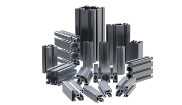
Industry-Standard Cross-Sections
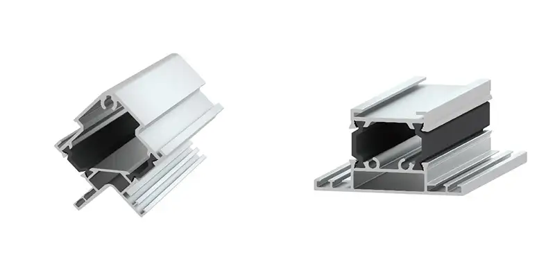
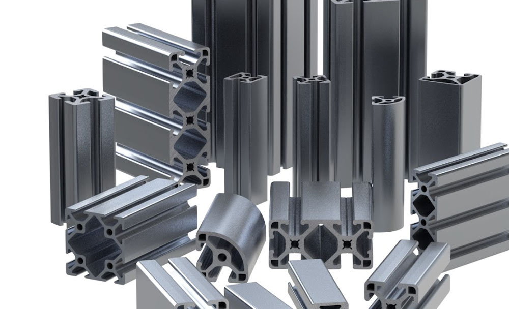
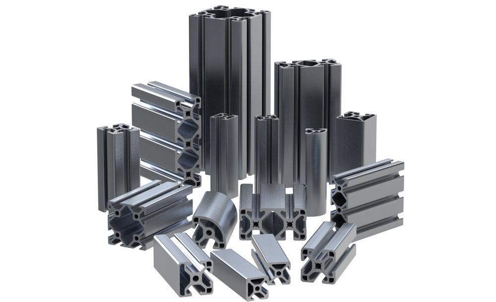
- Common Dimensions: 40×40mm, 45×45mm, 30×60mm, 50×50mm — compliant with DIN 610 or GB/T 6892.
- Slot Configuration: Typically 8mm T-slot or 10mm trapezoidal groove — compatible with universal fastening systems (corner brackets, T-nuts, end caps).
- Wall Thickness: 1.5mm–3.0mm — optimized for strength-to-weight ratio in non-critical applications.
Surface Treatment Specifications
- Anodized Finish: AA10–AA15 (10–15μm) per ISO 7599; withstands ≥500 hours neutral salt spray — standard for pharmaceutical and medical-grade profiles.
- Powder Coated Finish: 60–80μm thickness, ISO 8501-1 Sa2.5 surface preparation, adhesion rating ≥ Class 1 (cross-hatch test) — selected for aesthetic or chemical-resistant zones.
- Surface Cleanliness: Ra ≤ 1.2μm — free of burrs, drips, embedded particulates, or surface defects.
Typical Integrated Subsystems
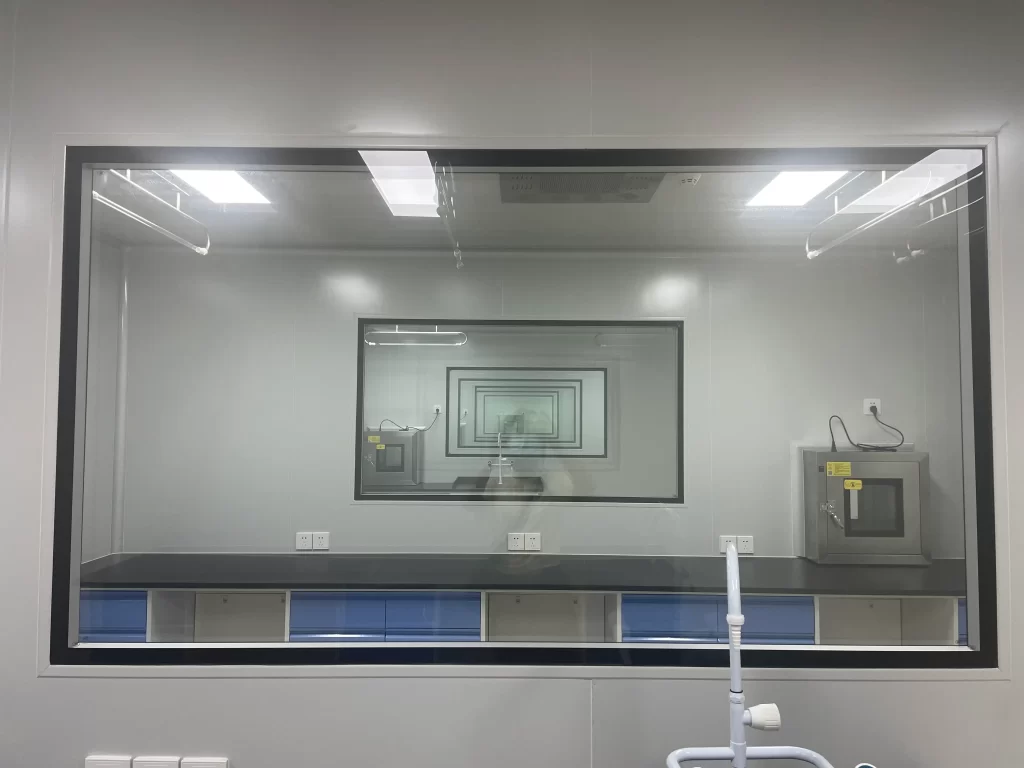
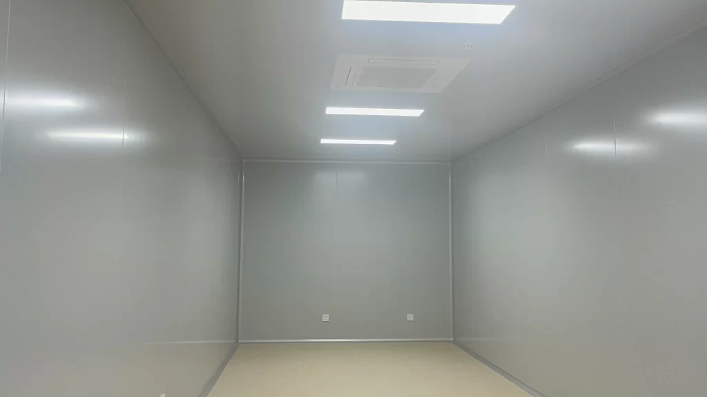
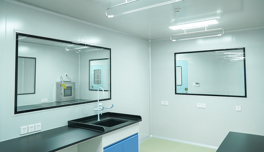
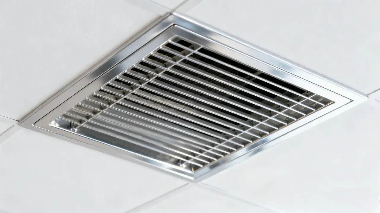
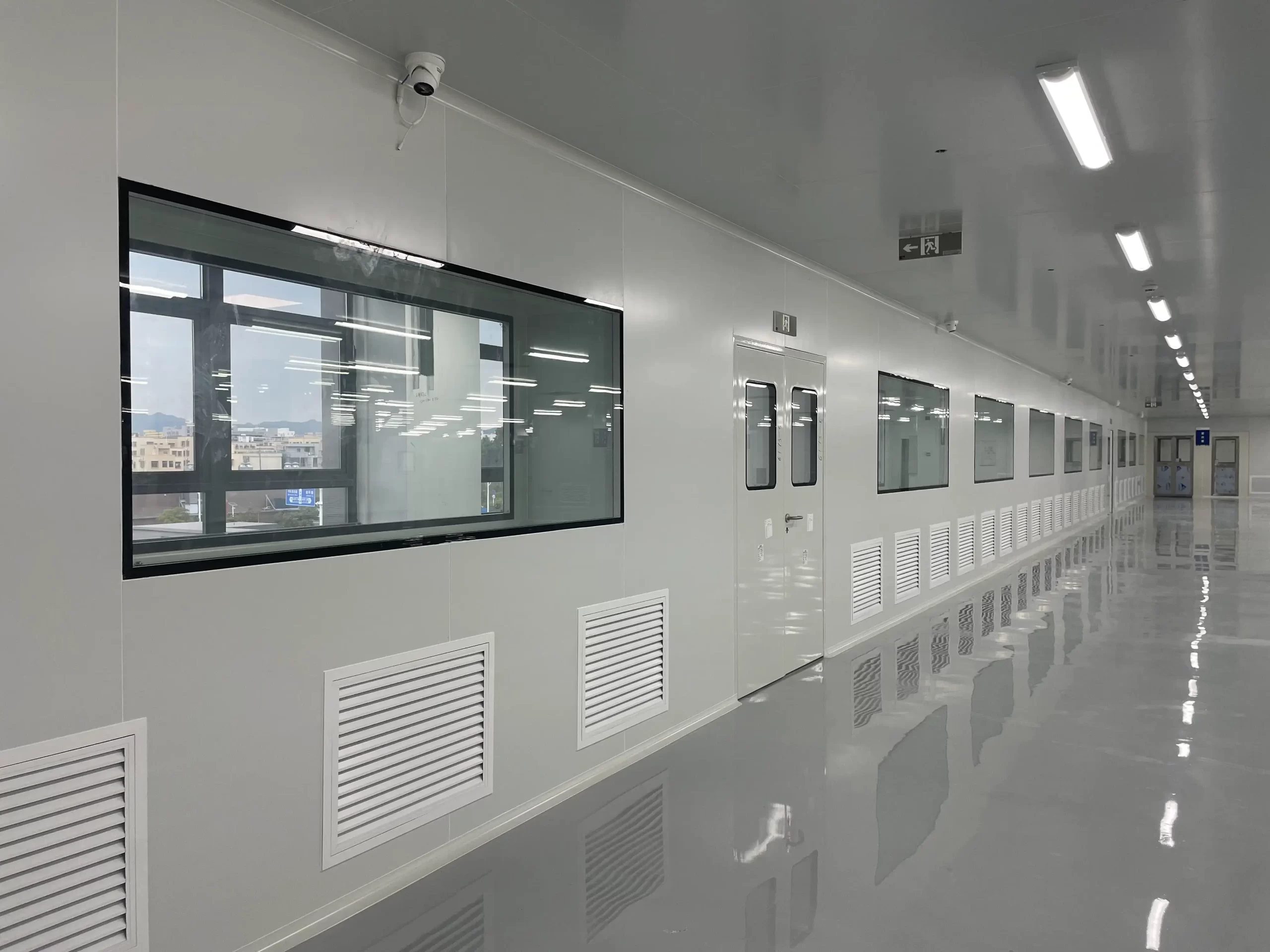
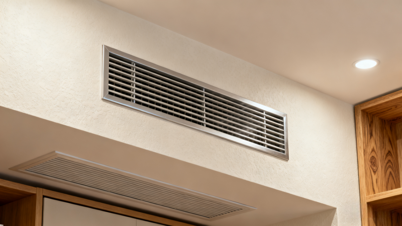
- Ceiling Support Systems: Pre-engineered interfaces for FFU, lighting, and blind panel integration — core application of ceiling extrusions.
- Return Air Walls: Integrated HEPA filter frames and differential pressure monitoring ports.
- Equipment Support Frameworks: Standardized uprights and cross-members for platform and workstation construction.
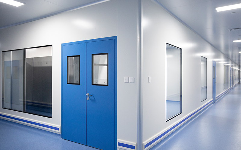
- Door Frame Assemblies: Pre-machined hinge locations and compression seal channels — forming compliant door frame systems.
2. Technical Boundaries of Applicability
Standard profiles are not universally applicable. Their use is constrained by specific performance thresholds:
Cleanliness Class Limitations
- Suitable For: ISO Class 5–8 environments (Class 100 to Class 100,000).
- Not Recommended For: ISO Class 4 and below (e.g., photolithography bays, aseptic filling suites) — where integrated sealing and ultra-low particle emission are mandatory — typically requiring engineered extrusions.
Spatial and Geometric Constraints
- Compatible With: Rectilinear, orthogonal geometries — no curves, bevels, or cantilevers.
- Incompatible With: Embedded equipment, non-standard utility routing, or spatially constrained installations.
Structural Load Limitations
- Static Load Capacity: ≤50kg/m (e.g., FFU + lighting + panel assemblies).
- Dynamic Load Capacity: Not suitable for high-vibration or impact-loading applications (e.g., centrifuges, compressors).
Regulatory Compliance Constraints
- Basic Compliance: Satisfies ISO 14644-1 for airborne particulate concentration and pressure differentials.
- Insufficient For: Advanced regulatory clauses — e.g., EU GMP Annex 1 2022 (“elimination of dead zones”), FDA 21 CFR Part 211 (“validated cleanability”) — requiring purpose-engineered pharmaceutical-grade profiles.
3. Inherent Engineering Limitations
While cost-effective and readily available, standard profiles exhibit inherent performance constraints:
Sealing Performance Dependent on Secondary Components
- Lacks integrated sealing features — requires discrete gaskets, clamping systems, or field-applied sealants.
- Assembly tolerance stack-up results in typical leakage rates of 0.5%–2.0% — significantly higher than engineered profiles (<0.01%).
- Joint interfaces create particle traps — incompatible with GMP “no dead zone” requirements.
Fixed Structural Properties Limit Local Optimization
- Uniform cross-section geometry prevents localized reinforcement at high-stress zones (e.g., equipment mounts, cantilever tips).
- Finite Element Analysis (FEA) indicates: under 50kg/m uniform load, a 40×40×2.0mm profile exhibits 3.2mm mid-span deflection — sufficient to disrupt FFU airflow uniformity.
Standardized Interfaces Constrain Functional Integration
- T-slot geometry cannot accommodate embedded fasteners, conductive paths, or sensor conduits.
- Equipment mounting requires adapter plates or secondary brackets — increasing alignment error and vibration transmission.
- Incompatible with integrated automation features (e.g., linear guide rails, pneumatic channels, ESD grounding).
Engineering Recommendation: Performance gaps may be partially mitigated through increased support density, upgraded connectors, and stringent installation controls — but fundamental material and geometric limitations remain immutable.
III. Engineered Cleanroom Aluminum Profiles: Performance-Driven Design Methodology

1. Engineered Profiles as Integrated Functional Solutions
In high-performance cleanrooms, engineered aluminum profiles transcend customization — they represent the convergence of structural integrity, environmental sealing, functional integration, and regulatory alignment within a single extruded component. This approach is essential for mission-critical applications in medical device manufacturing or semiconductor process environments.
Customizable Design Parameters
- Cross-Section Geometry: Asymmetric profiles, radiused transitions, beveled edges, cantilevered structures.
- Variable Wall Thickness: Localized reinforcement (+30% thickness at load interfaces), tapered sections.
- Functional Channels: Embedded wiring conduits (Φ6–Φ10), dual-seal grooves, magnetic or snap-fit mounting rails.
- Pre-Embedded Features: Stainless steel threaded inserts, carbon fiber ESD strips, copper grounding foils, RFID cavities.
Supported Engineering Deliverables
- Design Formats: DWG, STEP (ISO 10303), SolidWorks assemblies.
- Tolerance Specifications: Critical dimensions ±0.05mm (e.g., seal groove width, insert locations); non-critical ±0.1mm.
- Material and Process Documentation: Alloy designation, temper condition, surface roughness, cleanliness class.
2. Engineering Scenarios Requiring Engineered Profiles
The following conditions necessitate engineered profiles — not as a premium option, but as a technical imperative:
Structural Integration in Complex Geometries
- Curved Ceiling Systems: Semiconductor utility zones requiring aerodynamic contour matching to prevent flow separation — incompatible with standard ceiling extrusions.
- Angled Wall Transitions: BSL-3/4 laboratories with non-orthogonal interfaces — standard profiles cannot achieve air-tight alignment.
- Extended Cantilevers: Unsupported spans >1.5m — require torsional reinforcement and deflection control.
- Heavy Equipment Integration: Units exceeding 100kg (e.g., autoclaves, filling machines) — demand embedded structural reinforcement and vibration isolation — exceeding capabilities of standard cleanroom extrusions.
Monolithic Sealing for High-Integrity Environments
- Containment Laboratories (BSL-3/4): Require air leakage rates <0.01% — achieved through dual-integrated seal channels.
- Aseptic Processing Zones: FDA mandates “continuous, non-porous, cleanable surfaces” — enabled by welded and polished engineered profiles.
- Negative Pressure Isolation Suites: Require reverse-seal geometry to prevent internal contaminant egress.
Functional Integration for Smart Cleanrooms
- Embedded Sensor Networks: Internal routing for temperature, humidity, pressure, and particle counters — eliminating external cable interference.
- Integrated Linear Motion Systems: Precision guide rails (±0.1mm) for automated doors or equipment — seamlessly incorporated into door frame extrusions.
- Pneumatic and Utility Conduits: Pre-embedded tubing (Φ4–Φ8) with quick-connect interfaces.
- ESD Grounding Systems: Surface resistivity <1×10⁶Ω — compliant with SEMI E78 — critical for electronics-grade profiles.
Regulatory Alignment Through Design
- EU GMP Annex 1 (2022): “Minimization of particle shedding and elimination of dead zones” — requires radiused edges (R≥3mm), no recesses.
- FDA 21 CFR Part 211: “Surfaces shall not adsorb or leach contaminants” — demands Ra≤0.8μm finish with steam-sealed anodized aluminum.
- ISO 14644-3: Leak testing protocols — engineered profiles can incorporate test ports and sensor interfaces.
3. Development Process and Quality Assurance
Engineered profile development follows a rigorous, phase-gated methodology to ensure performance predictability and traceability.
Phase 1: Requirements Definition
- Deliverable: Technical Specification Document defining:
- Static and dynamic load spectra (with 1.5–2.0x safety factor).
- Seal performance criteria (leak rate, test methodology).
- Cleaning compatibility (CIP/SIP, chemical resistance).
- Interface inventory (mechanical, electrical, fluidic, control).
Phase 2: Topology Optimization and Simulation
- Structural Topology Optimization: Maximizes moment of inertia and torsional rigidity within material constraints.
- FEA Static Analysis: Validates deflection < L/500 under maximum load — preserving equipment alignment and airflow integrity.
- Modal Analysis: Ensures first natural frequency >1.5x maximum equipment excitation frequency (e.g., >75Hz for 50Hz fans).
- Thermal-Structural Coupling: Simulates ±15°C thermal expansion — verifies seal groove integrity under operational temperature variance.
Phase 3: Tooling Design and First Article Validation
- Die Material: H13 hot-work tool steel — rated for ≥50,000m extrusion life.
- First Article Validation:
- CT Scanning: Detects internal voids, inclusions, wall thickness deviations (≤50μm resolution).
- CMM Inspection: 100% verification of critical dimensions within ±0.05mm.
- Surface Profilometry: Confirms Ra≤0.8μm finish — per GMP Annex 1 requirements.
Phase 4: Pilot Assembly and Performance Testing
- Simulated Installation: Validates assembly sequence, fastener torque, and gasket compression.
- Leak Testing:
- Smoke Penetration Test: Visual confirmation of seal continuity.
- PAO Integrity Test: Aerosol photometer quantification — leakage <0.01%.
- Pressure Decay Test: 500Pa for 10 minutes — pressure loss <5%.
Timeline and Cost Structure
- Development Lead Time: 3–8 weeks (geometry-dependent), inclusive of tooling.
- Tooling Investment: $5,000–$20,000 (amortized over initial 5,000–10,000m production run).
- Production Lead Time: 1–2 weeks post-tooling approval — unit cost $15–$40/m.
Engineering Recommendation: Initiate engineered profile development during conceptual design — ensure alignment with overall project schedule and avoid critical path delays.
IV. Materials Science: Alloy Selection and Surface Treatment for Cleanroom Performance
1. Engineering Significance of Aluminum Alloys
Alloy selection directly impacts strength, formability, corrosion resistance, and surface treatment compatibility.
6063-T5: The Standard for General Cleanroom Applications
- Composition: Si+Mg alloy — excellent extrudability, smooth surface finish, uniform anodizing response.
- Mechanical Properties: Tensile strength ≥160MPa, elongation ≥8%.
- Applications: 90% of structural cleanroom extrusions — ceiling systems, wall framing — static loads ≤50kg/m.
6061-T6: High Strength and Fatigue Resistance
- Composition: Mg+Si+Cu — solution heat-treated and artificially aged — high strength, excellent fatigue performance.
- Mechanical Properties: Tensile strength ≥265MPa, yield strength ≥240MPa.
- Applications: High-vibration equipment mounts, heavy-duty door frame systems, long-span beams.
6005A-T6: Optimized for Long, Unsupported Spans
- Composition: Mn+Si — superior extrusion characteristics, higher tensile strength.
- Mechanical Properties: Tensile strength ≥270MPa — suitable for spans exceeding 3m.
- Applications: Cleanroom-grade extrusions for long-span ceilings, cantilevered equipment platforms.
2. Surface Treatment and Cleanliness Control
Surface finish governs particle emission, chemical resistance, and biocompatibility.
Anodizing Thickness and Sealing Methods
- Thickness Selection:
- 10μm: Standard for medical and electronics applications.
- 15μm: High-corrosion environments (e.g., CIP zones, acid/alkali exposure).
- Sealing Process:
- Hot Water Sealing (Steam): Porosity <5%, zero metal ion leaching — preferred for sterile zones — ideal for medical-grade profiles.
- Cold Sealing (Nickel-based): Lower cost — but risk of Ni²⁺ leaching — prohibited in direct drug contact zones.
Surface Roughness Control
- Standard Requirement: Ra ≤ 1.2μm (per ISO 14644-1).
- High-Performance Requirement: Ra ≤ 0.8μm (per EU GMP Annex 1) — minimizes particle adhesion and residue — essential for pharmaceutical-grade profiles.
- Measurement Method: Surface profilometer — sampling length ≥4mm, 5-point average.
3. Material Cleanliness Validation Protocols
Multi-dimensional validation is required for regulated environments.
Particle Emission Testing (ASTM F50/F51)
- Method: Simulated wiping (lint-free cloth + IPA) and airflow exposure (0.45m/s) — particle collection and counting.
- Acceptance Criteria: <100 particles/cm² ≥0.5μm — aligned with ISO Class 5.
Biocompatibility Testing (USP <87>/<88>)
- Cytotoxicity: Elution method — cell viability ≥70%.
- Sensitization: Guinea Pig Maximization Test (GPMT) — no erythema or edema.
- Applications: Aseptic filling, implantable device manufacturing — mandatory for medical-grade profiles.
Extractables Analysis (GC-MS)
- Method: 24-hour extraction in ethanol/water — GC-MS quantification of organic residues.
- Compliance: Meets FDA 21 CFR Part 211 — “no introduced contaminants.”
- Typical Limit: TOC <10μg/cm².
Material Selection Mnemonic: Light loads → 6063 | Heavy loads → 6061 | Long spans → 6005A Sterile zones → steam-sealed | Corrosive zones → 15μm | Biocompatible → USP-compliant
V. Structural Engineering: Mechanical Performance, FEA, and Failure Prevention
1. Mechanical Optimization Principles
Custom profiles aim to maximize structural efficiency with minimal material usage.
Maximizing Moment of Inertia (I-value)
- Cavity Placement: Position material away from the neutral axis — e.g., “C-section + stiffener” offers 40% higher I than solid square.
- Case Comparison: Standard 40×40 square: I=21.3cm⁴ → Custom “C+seal groove”: I=38.7cm⁴ → 45% reduction in deflection.
Local Reinforcement Design
- Equipment Mount Zones: Increase wall thickness by 30% (e.g., 2.0mm → 2.6mm) to mitigate stress concentration.
- Bolt Holes: Add annular stiffeners — edge distance ≥2x bolt diameter.
2. Finite Element Analysis (FEA) in Profile Design
FEA serves as the digital twin for validating performance prior to tooling.
Static Analysis
- Load Cases: Self-weight + equipment + dynamic pressure (e.g., FFU backpressure).
- Acceptance Criteria: Maximum deflection < L/500 — no interference with door operation or FFU performance.
Modal Analysis
- Objective: First natural frequency >1.5x maximum equipment excitation frequency.
- Example: Fan at 50Hz → profile frequency >75Hz.
Thermal-Stress Coupling
- Scenario: ±15°C operational temperature swing.
- Risk: Thermal expansion induces seal groove deformation → increased leakage.
- Mitigation: Incorporate expansion joints or flexible sealing materials.
3. Common Failure Modes and Prevention Strategies
Bolt Hole Tear-Out
- Cause: Insufficient edge distance, lack of reinforcement, over-torquing.
- Prevention: Edge distance ≥2d (d = bolt diameter), add backing plates, torque per ISO 898-1.
Seal Groove Deformation
- Cause: Unsupported groove base collapses under compression.
- Prevention: Add longitudinal stiffeners ≥50% of groove depth.
Interface Misalignment
- Cause: CTE mismatch (Al: 23.6×10⁻⁶/°C vs. Steel: 11.7×10⁻⁶/°C).
- Prevention: Allow 5mm expansion per 10m span — or use flexible connectors.
Structural Design Principle: Control deflection — Avoid resonance — Accommodate expansion — Distribute stress.
VI. Manufacturing and Quality Control
1. Extrusion Process Impact
Extrusion quality dictates dimensional accuracy, surface finish, and mechanical properties.
Die Temperature Control
- Optimal Range: 450–500°C — excessive heat causes surface tearing; insufficient heat increases extrusion force.
- Surface Finish: Die polished to Ra≤0.2μm → profile surface Ra≤0.8μm.
Pull Speed
- Balance Point: 2–4m/min — excessive speed causes wall thickness variation; too slow reduces throughput.
- In-line Monitoring: Laser thickness gauge — closed-loop feedback control.
In-line Quenching
- T5 Condition: Air-cooled — moderate strength — suitable for 6063.
- T6 Condition: Water-quenched + artificially aged — high strength — for 6061/6005A.
2. Tolerance Control and Inspection Methods
Cleanroom profiles demand tighter tolerances than architectural aluminum.
Key Dimensional Tolerances
- Standard: ±0.1mm (e.g., outer profile, slot width).
- High Precision: ±0.05mm (e.g., seal grooves, embedded insert locations).
Inspection Tools
- CMM: ±0.002mm accuracy — 100% first-article inspection.
- Laser Scanning: Rapid 3D point cloud generation — deviation mapping vs. CAD.
- Optical Profilometer: Cross-section contour analysis — essential for complex geometries.
100% vs. Sampling Inspection
- 100% Inspection: Load-bearing, sealing, and embedded components.
- Sampling (AQL 1.0, ISO 2859-1): Non-critical decorative elements.
3. Cleaning and Packaging Standards
Post-manufacturing processes determine “as-shipped cleanliness.”
Cleaning Process
- Ultrasonic Wash: Removes machining oils and aluminum particulates.
- DI Water Rinse: Resistivity ≥15MΩ·cm — zero ionic residue.
- Hot Air Dry: 80°C × 30 minutes — moisture content <0.1%.
Cleanroom Packaging
- Inner Packaging: Dual-layer PE bags (inner layer anti-static) — sealed in Class 100 environment.
- Outer Packaging: Corrugated cartons with corner protectors — labeled “Cleanroom Use Only.”
- Shipping: Dedicated compartment — no stacking or deformation.
Manufacturing Quality Principle: Precision dies — Controlled pull — Accurate quench — Tight tolerances — Full inspection — Clean packaging.
VII. Industry Compliance and Validation
1. Industry-Specific Requirements
Pharmaceutical (GMP Annex 1)
- No Dead Zones: No recesses or sharp edges (minimum R3mm radius).
- Cleanability: Surface Ra≤0.8μm — seamless or continuously welded joints.
- No Shedding: Anodized film adhesion ≥5B (cross-hatch test).
- Validation Required: Particle, microbial, and endotoxin cleaning validation reports — mandatory for pharmaceutical-grade profiles.
Semiconductor (SEMI F73)
- Low Outgassing: GC-MS testing — TVOC <1μg/cm².
- No Metallic Contamination: Zero detectable Cu, Fe, Ni residues (ICP-MS).
- ESD Control: Surface resistivity 10⁴–10⁹Ω (four-point probe) — core requirement for electronics-grade profiles.
Medical (ISO 13485)
- Biocompatibility: Compliance with USP <87>/<88> or ISO 10993.
- Traceability: Full batch traceability from melt → extrusion → surface treatment.
- Nickel-Free: No nickel-sealed anodizing — allergen risk mitigation — baseline for medical-grade profiles.
2. Validation and Audit Essentials
Material Traceability
- Documentation: EN 515 mill certificates, heat treatment reports, surface treatment logs.
- Batch Tracking: Laser-etched batch ID per linear meter — full digital traceability.
Cleaning Validation Report
- Particles: Wipe test + particle counter — <100 particles/cm² ≥0.5μm.
- Microbial Load: Contact plate method — <1 CFU/25cm².
- Endotoxin: LAL test — <0.25EU/mL (if applicable).
Post-Installation Testing
- Air Tightness: Pressure decay test — 500Pa for 10 minutes → pressure loss <5%.
- Particle Scan: Per ISO 14644-3 — scan all joints and interfaces.
3. Common Audit Findings and Responses
Finding 1: Unsealed or Non-Continuous Joints
- Response: Provide seal design drawings — demonstrate “monolithic profile + pre-compressed gasket” solution.
Finding 2: Surface Scratches Exceeding Specification
- Response: Submit factory surface inspection records (Ra values, visual documentation).
Finding 3: Missing Material Certifications
- Response: Maintain full supply chain documentation — including RoHS, REACH, and mill test reports.
Compliance Core Principle: Design for compliance — Manufacture with traceability — Validate with data — Close the audit loop.
VIII. Technical Comparison: Standard vs. Engineered Profiles
| EVALUATION CRITERIA | STANDARD PROFILES | ENGINEERED PROFILES |
|---|---|---|
| Lead Time | 3–7 days | 3–8 weeks (first order); 1–2 weeks thereafter |
| Unit Cost | $8–$15/m | $15–$40/m (incl. tooling amortization) |
| Design Flexibility | Low | High (fully engineered to print) |
| Sealing Performance | Add-on dependent — 0.5–2% leak | Integrated — <0.01% leak |
| Load Capacity | ≤50kg/m (static) | Up to 200kg/m+ — supports dynamics |
| Compliance Adaptability | Basic ISO 14644 | Meets GMP/FDA/BSL/SEMI clauses |
| Expandability | High (standard interfaces) | Medium (requires pre-planned ports) |
| Maintenance & Replacement | Easy — off-the-shelf | Requires tooling or CAD retention |
| Material Traceability | Batch ID typically provided | Full process & material traceability |
| Failure Prevention | Relies on installation QC | Validated via FEA & prototype testing |
IX. Real-World Case Studies: Engineering Decisions That Define Project Success
Case 1: mRNA Vaccine Filling Line — Engineered Profile with Aerodynamic Curves and Pre-Embedded FFU Mounts
- Challenge: Right-angle joints induced vortices — particle accumulation in critical filling zones.
- Solution:
- FEA-optimized cross-section: 50mm radius transitions — eliminated flow separation.
- Integrated dual-seal groove: EPDM pre-compression — leakage <0.005%.
- Pre-embedded FFU mounting clips: ±0.1mm alignment — 50% faster installation.
- Result: 60% reduction in particle counts — zero FDA 483 observations — benchmark for pharmaceutical-grade profile implementation.
Case 2: Semiconductor Front-End Cleanroom — Standard Beams + Engineered ESD Interfaces
- Challenge: Standard profiles exhibited surface resistance >1×10¹²Ω — ESD attracted particles, reducing yield.
- Solution:
- Retained standard 45×45 beams for cost efficiency.
- Engineered equipment interfaces with embedded carbon fiber — surface resistance 1×10⁶Ω.
- Pre-embedded copper grounding foil — resistance <0.1Ω.
- Result: Eliminated ESD-related scrap — 0.8% yield improvement — $2.3M annual savings — exemplifies precision of electronics-grade profiles.
Case 3: Hybrid Operating Room in Tertiary Hospital — Engineered Door Frame with Integrated Rails, Emergency Release, and Magnetic Seals
- Challenge: Compact space required support for 200kg DSA equipment while maintaining air-tightness.
- Solution:
- Profile integrated linear rails (±0.05mm), mechanical emergency release, dual magnetic seals.
- Passed 200,000-cycle durability testing — consistent leakage <0.01%.
- Result: Zero leakage over 24 months — CE MDR Class IIa certified — industry benchmark for medical-grade + door frame profile integration.
X. Decision Framework: The 5-Step Engineering Selection Process
Step 1: Define Performance Boundaries
- Cleanliness class (ISO Class?)
- Load spectrum (static/dynamic/impact?)
- Seal performance target (leak rate?)
- Regulatory standard (GMP? SEMI? ISO 13485?)
Step 2: Map Functional Requirements
- Annotate all equipment interfaces, moving components, cleaning paths, maintenance access points.
- Identify “must-engineer” zones (sealing, structural, functional integration).
Step 3: Assess Manufacturing Feasibility
- Conduct joint DFM review with supplier: Can the section be extruded? Can the die be manufactured? Can tolerances be held?
- Model lifecycle cost: Compare standard vs. engineered — include rework, audit risk, downtime.
Step 4: Validate Prototype Performance
- Produce 3–5m sample — execute:
- Leak testing (PAO/Smoke)
- Load testing (1.5x design load)
- Cleanability validation (wipe + particle count)
Step 5: Compile Documentation Package
- Material certifications, test reports, installation guides, audit checklists.
- Ensure end-to-end traceability: Design → Manufacture → Validate → Audit.
XI. Conclusion: Profile Selection Is Systems Engineering — Not Procurement
Selecting cleanroom aluminum profiles is fundamentally an exercise in structural mechanics, materials science, manufacturing engineering, and regulatory compliance. This decision must be made during conceptual design — not delegated to procurement. Involve engineers, compliance officers, and suppliers from day one.
- Standard Profiles Are Tools — for routine, low-risk, cost-driven projects — like basic cleanroom frameworks.
- Engineered Profiles Are Solutions — for high-complexity, high-compliance, high-performance needs — like medical or electronics-grade profiles.
- Hybrid Strategies Are Optimal — standardize primary structure, customize critical nodes — achieving Pareto efficiency in cost vs. performance.
The ultimate goal? A leak-free, cleanable, stable, fully compliant physical backbone — enabling high-value manufacturing and life-saving research.
-
 Cleanroom Glass Windows Are The Key to Maintaining a Clean Environment
 -
 Top Aluminium Profile Manufacturers in China: Leading the Global Market
 -
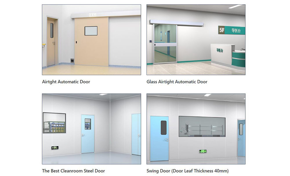
 The Evolution of Air Tight Sliding Doors
 -
 AHU Aluminium Profile: A Comprehensive Guide
 -
 The Importance of Choosing the Right Cleanroom Door in Vietnam
 -
 The Benefits of Hospital Automatic Doors: Enhancing Efficiency and Safety
 -
.jpg) The Best Bathroom Door Manufacturers - Unlocking Endless Possibilities!
The Best Bathroom Door Manufacturers - Unlocking Endless Possibilities! -
 Unlock the Possibilities with AJ Manufacturing Doors
 -
 Make a Statement with Manufactured Home Interior Doors!
 -
 what is aluminum profile? Aluminum Profiles for Your Home is the best option
-
 How to Extend the Life of Your Exterior Steel Door
 -
 What Are the Best Materials for AC Vent Covers
 -
 Ceiling Vent Covers Labeled Fire-Rated? Here’s How to Verify
 -
 Upgrading Lab Doors: When to Replace vs. When to Retrofit?
 -
 Stainless Steel Door vs. Alternatives in Cleanrooms
 -
 Ceiling Vent Care Tips to Boost HVAC Efficiency Year Round
 -
 How Air Dampers Drive Efficiency in High Performance Buildings
 -
 Why Semiconductor Manufacturing Can’t Function Without Cleanrooms
 -
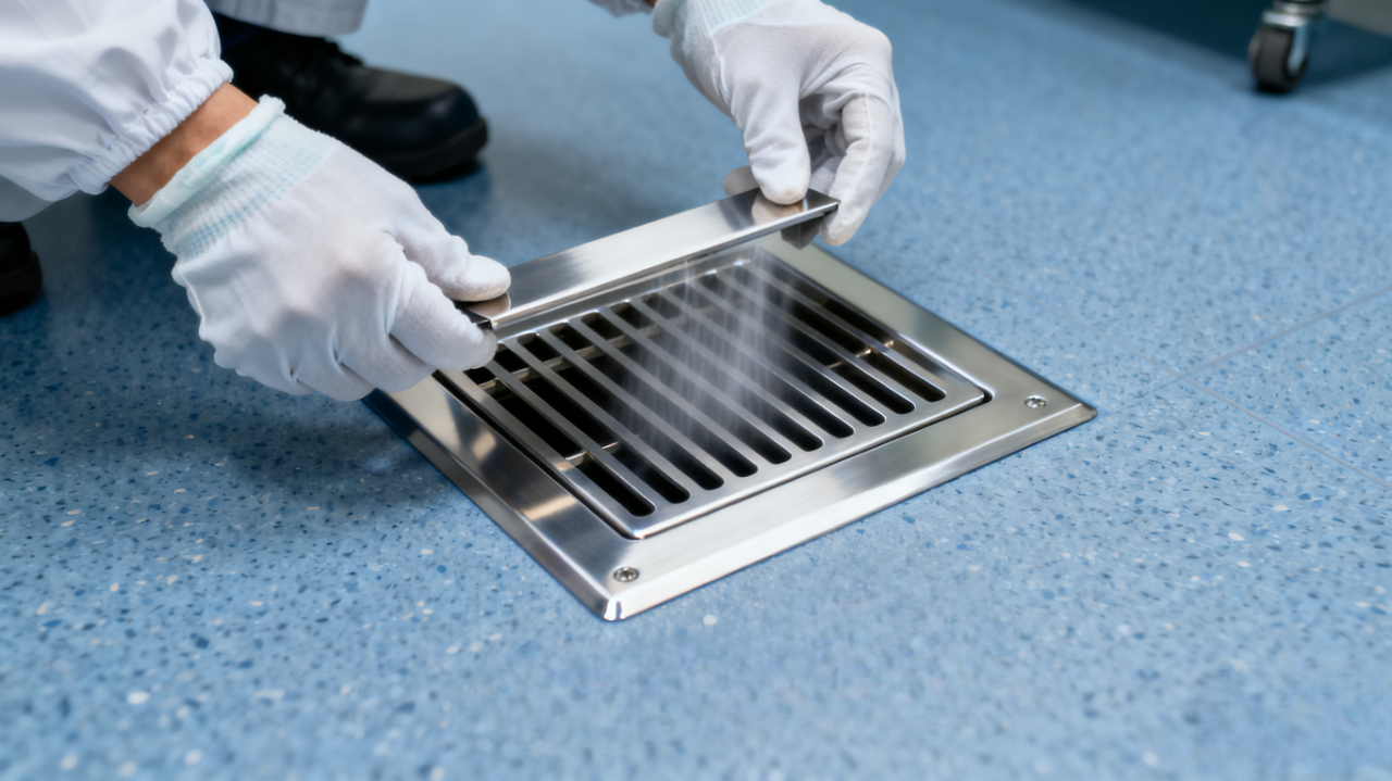 How to Select the Right Floor Vent for Cleanrooms
 -
 How to Clean and Maintain AC Registers for Peak HVAC Performance


-

Home
-

Tel
-

Email
-

Contact


Guangzhou Yizhong Aluminum Industry Co., Ltd.
We are always providing our customers with reliable products and considerate services.
We are always providing our customers with reliable products and considerate services.
Speak Your Mind