
5 HVAC Diffuser Mistakes That Break Laminar Flow in Cleanrooms
Cleanrooms are mission-critical environments in high-tech industries such as pharmaceuticals, semiconductors, and biotechnology. The stability of their environmental controls directly determines product yield and safety. Within the air handling system of a cleanroom, the HVAC (Heating, Ventilation, and Air Conditioning) system is the backbone for maintaining cleanliness, temperature, humidity, and pressure differentials. At the heart of this system lies the HVAC diffuser—the final point where conditioned air enters the space. As the origin of airflow, its design and layout profoundly influence overall airflow patterns.
Despite significant investments in high-efficiency filters, airflow volume, and pressure control, many projects overlook the diffuser’s pivotal role in sustaining unidirectional (laminar) airflow. This article uncovers five common HVAC diffuser design mistakes in cleanroom engineering—errors that often lead to airflow short-circuiting and disruption of laminar flow, ultimately undermining cleanroom certification and operational reliability.
Fundamentals of Cleanroom Airflow Patterns
The Core Objective of Cleanroom Airflow
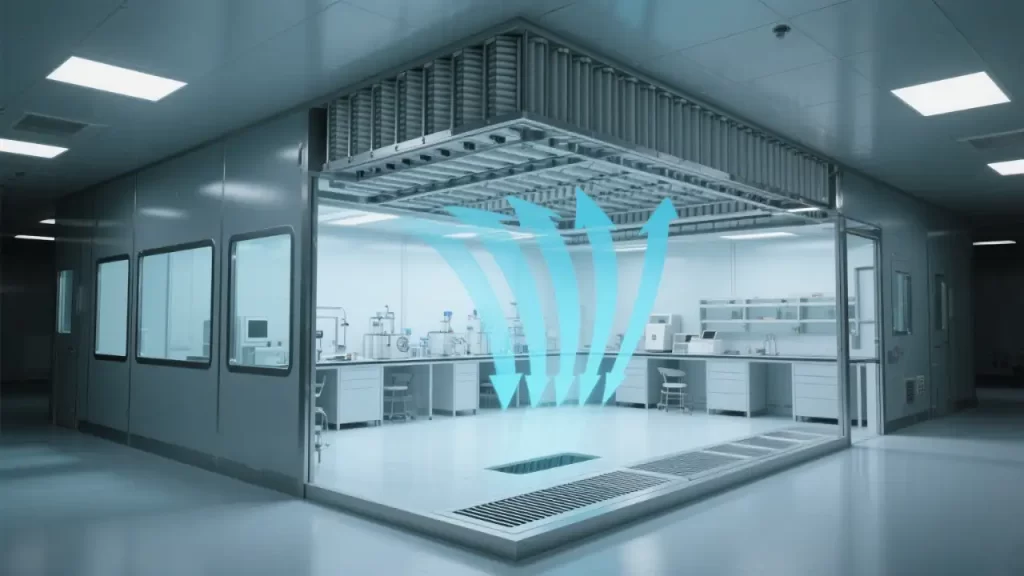
The primary goal of a cleanroom is to control airborne particulate concentration in compliance with ISO 14644 standards. In high-grade environments—ISO Class 5 and above—vertical unidirectional airflow is typically required. This means air flows uniformly downward from a ceiling densely populated with HEPA or ULPA filters, creating a "piston-like" effect that sweeps contaminants toward floor-level return or exhaust systems.
The success of this airflow strategy hinges on three key factors: uniformity, path integrity, and low turbulence. Any factor that causes airflow deviation, swirling eddies, or premature recirculation compromises the system. Localized "dead zones" or particle accumulation can result—posing serious risks to process integrity.
Laminar vs. Non-Unidirectional Airflow Systems
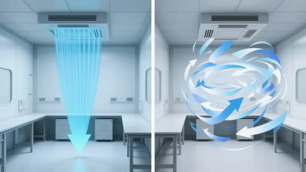
In lower-grade cleanrooms (ISO Class 6–9), non-unidirectional (or turbulent-mixing) airflow is often used. Here, high air change rates dilute contaminants through mixing. However, this approach lacks the directional control needed for critical processes.
In contrast, unidirectional flow systems are defined by strict performance criteria:
- Average air velocity: typically 0.3–0.5 m/s
- Velocity uniformity: standard deviation ≤15%
- Flow parallelism: deviation from vertical ≤15°
Achieving these metrics depends heavily on the type, arrangement, and integration of HVAC diffusers with the return air system. While turbulent mixing may suffice for general cleanliness, only laminar flow can guarantee contamination-free conditions over critical work zones.
The Role of HVAC Diffusers in Cleanroom Design
Types of Diffusers and Their Applications
Common diffuser types in cleanrooms include:
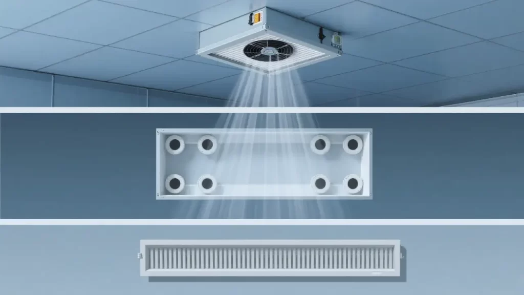
- Fan Filter Units (FFUs)
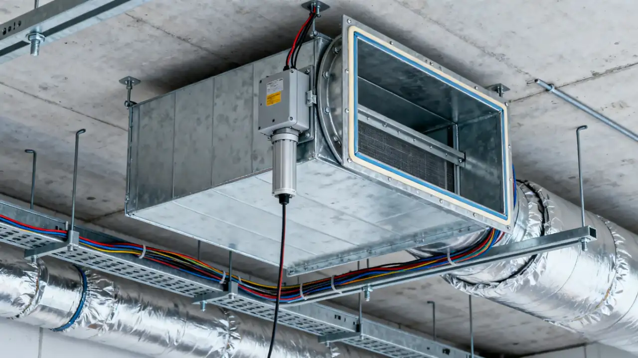
- Plenum-based supply systems
- Linear slot diffusers
FFUs have become the gold standard in high-grade cleanrooms due to their integrated fans, modular scalability, and ease of maintenance. Plenum systems distribute air through a pressurized chamber to multiple ceiling-mounted filters—ideal for large areas or facilities with structural load constraints. Linear slot diffusers, often used in corridors or less critical zones, promote mixing flow and are unsuitable for unidirectional applications.
Selecting the right type requires a holistic assessment of cleanliness class, ceiling height, equipment layout, and lifecycle maintenance needs.
Why the Diffuser Is More Than Just an Outlet
An HVAC diffuser is not merely a "vent"—it is the starting point of the entire cleanroom’s aerodynamic behavior. Its design dictates the initial velocity, direction, and spread of the air jet. Even with a perfectly engineered upstream system, a poorly designed diffuser can generate turbulence or uneven dispersion at the point of delivery, undermining downstream airflow stability.
Treating diffuser selection as an afterthought—or a cosmetic detail—is a recipe for failure. It must be treated as a central component of system design, not a final accessory.
5 Common Design Errors That Disrupt Laminar Flow
1. Using Non-Laminar Diffusers in High-Grade Zones
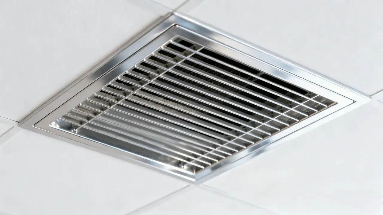
One of the most widespread mistakes is installing conventional swirl diffusers or grilles in ISO Class 5 or higher environments. These diffusers—designed for office buildings—are meant to promote air mixing, not laminar flow. Their radial discharge patterns create immediate entrainment and turbulence, destroying the vertical piston effect.
The correct solution? A fully covered ceiling of Fan Filter Units (FFUs) or equivalent laminar supply devices. Industry best practice recommends that supply coverage occupy at least 80% of the ceiling area to minimize interference and sustain true unidirectional flow. As stated in IEST-G-CC006, only diffusers capable of delivering uniform, low-turbulence airflow should be used in unidirectional cleanrooms.
2. Excessive Diffuser Spacing Leading to Velocity Drop
Spacing between diffusers is a critical factor in airflow uniformity. When units are placed too far apart, the central zone between them experiences significant velocity decay due to jet dissipation—creating a "speed valley."
Computational Fluid Dynamics (CFD) simulations show that when FFU spacing exceeds 1.2 meters, wind speed at midpoints can drop more than 40% below the level directly beneath the units—far exceeding the ±15% uniformity tolerance specified in ISO 14644-4.
To prevent this, spacing should be carefully calculated based on room height, diffuser performance, and target velocity. A general rule of thumb: keep spacing under 1.0 meter, and always validate the layout with CFD modeling during the design phase.
3. Poor Coordination Between Supply and Return Air Causing Airflow Short-Circuiting
Airflow short-circuiting is one of the most frequent performance failures in cleanrooms. It occurs when supply air is captured by a nearby return or exhaust before it fully blankets the workspace.
This often results from poor layout decisions—such as placing return grilles directly beneath supply diffusers or locating large exhaust devices too close to the supply zone. Aerodynamically, high-velocity supply jets create low-pressure zones near return openings, effectively "sucking in" the fresh air before it does its job.
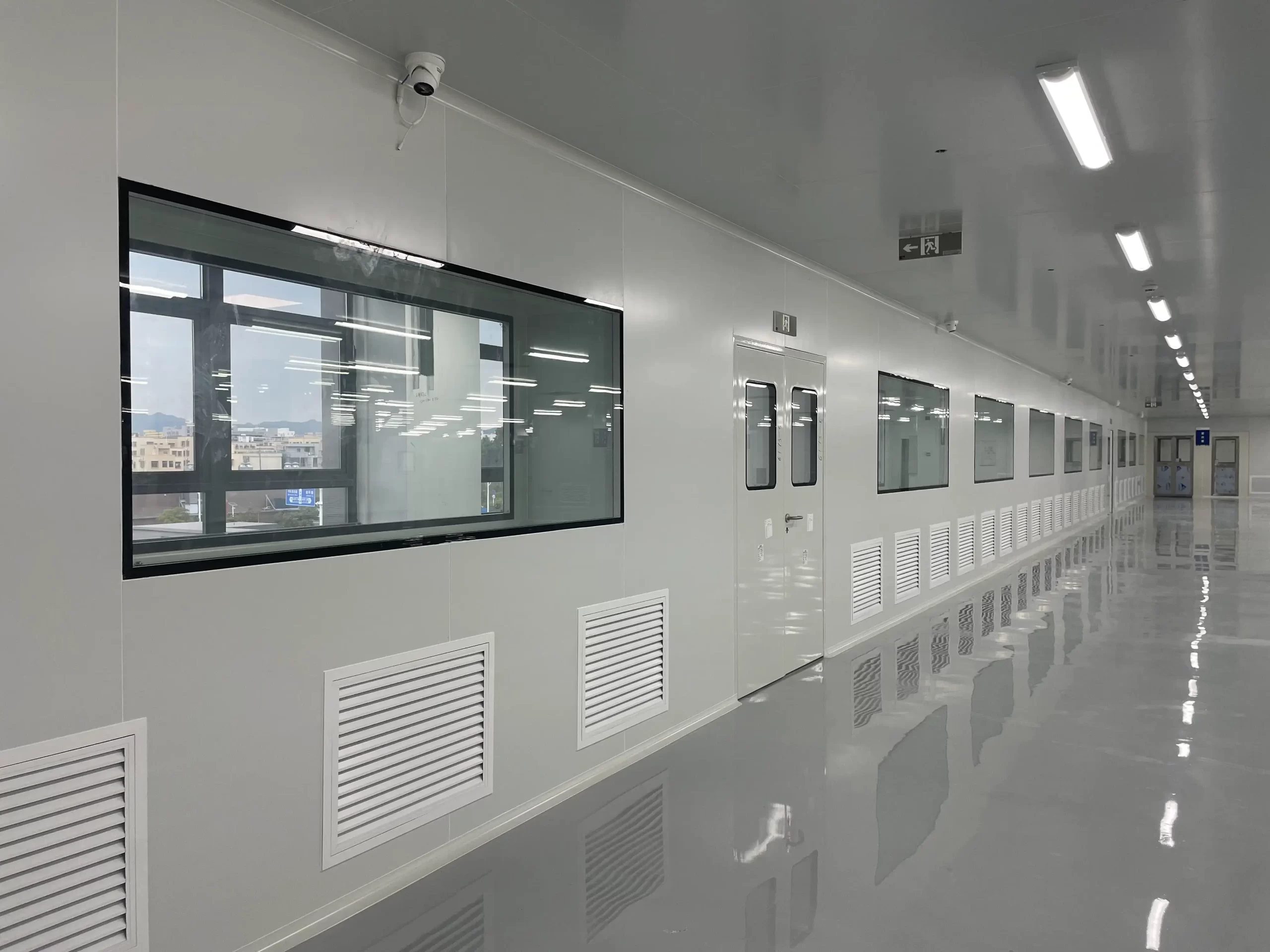
The fix? Follow the "top-down, bottom-up" principle: supply air from the ceiling, return it from low-level wall grilles or dedicated return plenums. This ensures air travels the full vertical path across the clean zone before exiting—maximizing contaminant removal.
4. Ignoring Thermal Disturbances from Equipment
Process equipment—autoclaves, reactors, server racks—can generate substantial heat, creating thermal plumes that rise against the downward laminar flow. These buoyant currents deflect, distort, or even reverse local airflow, forming vortices and stagnant pockets.
For example, a single 1 kW device can produce a thermal plume of approximately 0.2 m³/s—enough to disrupt laminar flow in its vicinity.
Solutions include:
- Installing air curtains or baffles around heat sources
- Adding localized downflow to suppress rising hot air
- Incorporating equipment heat loads into CFD models early in design to anticipate and mitigate disruptions
Thermal management isn’t an afterthought—it’s part of airflow engineering.
5. Overlooking Filter Loading and Long-Term Airflow Degradation
Cleanroom performance must be sustainable—not just on day one, but over months and years. HEPA and ULPA filters accumulate particles over time, increasing resistance and reducing airflow. If the system lacks variable air volume (VAV) or variable frequency drives (VFDs), the result is a gradual decline in face velocity.
Eventually, velocity may fall below the minimum required for laminar flow (e.g., 0.25 m/s), leading to turbulence and particle accumulation. The problem often goes unnoticed until a failed particle count test reveals the issue—sometimes months after installation.
Smart design accounts for long-term airflow degradation. Implement continuous velocity monitoring, predictive maintenance schedules, and filter replacement protocols to ensure consistent performance throughout the system’s lifecycle.
Designing a High-Performance Cleanroom Diffuser System
HVAC Diffuser Selection Principles
Adopt a "grade-driven" selection approach:
- ISO Class 5 and below: Require full-coverage FFUs or equivalent laminar supply systems
- ISO Class 6–7: May use plenum systems, but must ensure uniform pressure distribution to avoid "proximity bias"—where areas near the fan receive more airflow than distant zones
All decisions should stem from rigorous load calculations and airflow simulations—not rules of thumb.
The Golden Rules of Diffuser Layout
Follow these three core principles:
- Maximize supply coverage – Aim for ≥80% ceiling coverage with diffusers
- Minimize obstructions – Avoid placing lights, ducts, or equipment directly under or between diffusers, as they disrupt airflow continuity
- Optimize supply-to-return pathways – Ensure air travels the longest, most complete path before exiting, avoiding shortcuts
Additionally, coordinate diffuser placement with structural elements (beams, columns) early in design to prevent last-minute compromises.
Validate with CFD Simulation
In today’s cleanroom design, CFD simulation is non-negotiable. A high-fidelity 3D model can predict airflow vectors, temperature gradients, and particle trajectories with remarkable accuracy.
Use CFD to:
- Identify potential dead zones, eddies, or short-circuit paths
- Test different equipment layouts or diffuser configurations
- Optimize for both performance and energy efficiency
A robust CFD report—including velocity vector plots, contour maps, and particle tracking animations—provides compelling evidence of system reliability to clients, regulators, and certification bodies.
On-Site Testing and Certification
After installation, rigorous field testing is essential:
- Smoke tests – Visualize airflow paths and detect short-circuiting or turbulence
- Air velocity mapping – Measure speed at grid points using thermal anemometers to assess uniformity
- Particle counting – Confirm compliance with ISO 14644-1 classification
All tests must follow ISO 14644-3 protocols and be documented in a formal qualification package. This isn’t just a compliance step—it’s proof that the system performs as designed.
FAQ
Q: What is the best HVAC diffuser for ISO Class 5 cleanrooms? A: Fan Filter Units (FFUs) with ≥80% ceiling coverage are the industry standard for maintaining laminar flow.
Q: How far apart should HVAC diffusers be spaced? A: For ISO Class 5 environments, spacing should not exceed 1.0 meter. CFD modeling is recommended to verify uniformity.
Q: Can laminar flow be maintained with a plenum system? A: Only if the plenum ensures uniform pressure distribution. FFUs are preferred for critical applications.
Q: How do you test if HVAC diffusers are working properly? A: Use smoke tests, velocity mapping, and particle counting per ISO 14644-3.
Conclusion: Elevating the Diffuser from Accessory to Core System
From Afterthought to Critical Component
HVAC diffusers are not mere endpoints—they are the lungs of the cleanroom. A well-designed diffuser system delivers stable, contamination-free environments with minimal energy use. The industry must shift from viewing diffusers as passive components to recognizing them as mission-critical elements, as vital as chillers, fans, or control systems.
Toward Integrated, Collaborative Design
Cleanroom success is a team effort. HVAC engineers must engage early with process, architectural, structural, and electrical teams. After all:
- Architectural layout determines equipment placement
- Structural beams affect diffuser positioning
- Process heat loads shape airflow behavior
Only through an integrated design approach can every decision—from concept to commissioning—serve the ultimate goal: flawless, predictable airflow.
The future of cleanroom design lies in data-driven decisions, simulation-first workflows, and cross-disciplinary collaboration. When we treat the diffuser not as a vent, but as the foundation of environmental control, we build cleaner, smarter, and more reliable facilities.
-
 Cleanroom Glass Windows Are The Key to Maintaining a Clean Environment
 -
 Top Aluminium Profile Manufacturers in China: Leading the Global Market
 -
 The Evolution of Air Tight Sliding Doors
 -
 AHU Aluminium Profile: A Comprehensive Guide
 -
 The Importance of Choosing the Right Cleanroom Door in Vietnam
 -
 The Benefits of Hospital Automatic Doors: Enhancing Efficiency and Safety
 -
.jpg) The Best Bathroom Door Manufacturers - Unlocking Endless Possibilities!
The Best Bathroom Door Manufacturers - Unlocking Endless Possibilities! -
 Unlock the Possibilities with AJ Manufacturing Doors
 -
 Make a Statement with Manufactured Home Interior Doors!
 -
 what is aluminum profile? Aluminum Profiles for Your Home is the best option
-
 How to Extend the Life of Your Exterior Steel Door
 -
 What Are the Best Materials for AC Vent Covers
 -
 Ceiling Vent Covers Labeled Fire-Rated? Here’s How to Verify
 -
 Upgrading Lab Doors: When to Replace vs. When to Retrofit?
 -
 Stainless Steel Door vs. Alternatives in Cleanrooms
 -
 Ceiling Vent Care Tips to Boost HVAC Efficiency Year Round
 -
 How Air Dampers Drive Efficiency in High Performance Buildings
 -
 Why Semiconductor Manufacturing Can’t Function Without Cleanrooms
 -
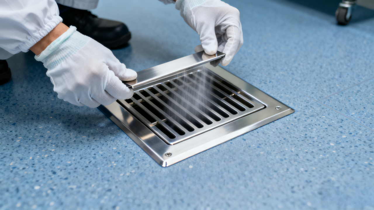 How to Select the Right Floor Vent for Cleanrooms
 -
 How to Clean and Maintain AC Registers for Peak HVAC Performance


-

Home
-

Tel
-

Email
-

Contact


Guangzhou Yizhong Aluminum Industry Co., Ltd.
We are always providing our customers with reliable products and considerate services.
We are always providing our customers with reliable products and considerate services.
Speak Your Mind